- DC/DC – Converters as Impedance Transformers
- MPPT – Algorithm
- Performance
- Conclusoin
- Literature
- Meeting Infineon
Did you know PV solar panels have a preferred load impedance for maximal power output?
For example, if you connect a zero ohm resistance (short) you will have U=0V and thus P=U*I=0W. If you increase the resistance more and more power will be drawn until a maximum is reached and the the power drops when your resistance reaches infinity and no current flows I=0A and thus P=U*I=0W. Somewhere in between those extremes, at a certain voltage to current ratio = output impedance, is the Maximum Power Point (MPP) where we can extract the maximum amount of power from the solar panel.
The actual characteristics of a solar panel can be seen in the following images:
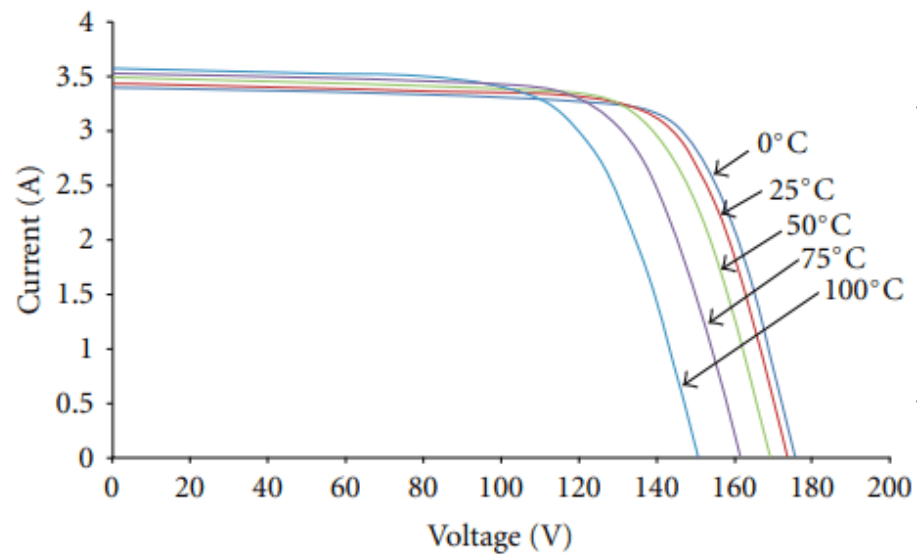
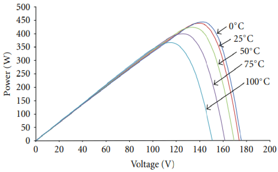
As seen in the images above, especially Fig 2, the MPP can change depending on the temperature of the solar panel. A solar optimizer is a device that tracks the MPP and draws the maximum amount of power from a solar-panel.
This project was part of a challenge from “Infineon Technologies Austria” in cooperation with “IndustryMeetsMakers” where our task was to design, build, implement and test such an optimizer.
DC/DC – Converters as Impedance Transformers
DC/DC converters are often used in power supplies to convert an input voltage to a desired output voltage with high efficiencies of >90%. They do so by quickly opening and closing a switch (transistor). Thus only a select amount of current is being drawn from the input of the DC/DC converter and applied to its output. So in other words a DC/DC converter can change the output impedance that the supply sees.
Two types of DC/DC converters are very famous for this task:
- Buck Converters can apply any voltage from zero or the input voltage to the output and thus can increase the impedance of the load.
- Boost Converters can apply the input voltage and higher voltages to the output and thus can decrease the impedance of the load.
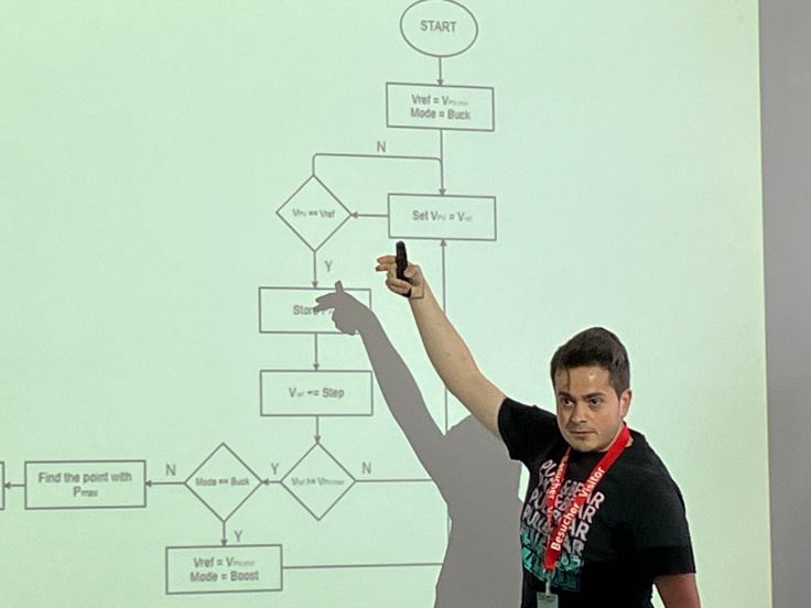
Figure 3 shows a typical buck-boost converter once in buck mode and once in boost mode. In Buck Mode the Transistor T1 limits the amount of current being drawn from the solar panel, charges up the magnetic flux of the coil, and T2 allows the discharge of the coil which briefly turns into a supply element for the load. In Boost Mode the T4 will almost short to ground, charging up the coil and allowing for a massive buildup of magnetic-flux field. T3 will then discharge the coil over the load which pumps a lot of current into the load and increases the output voltage.

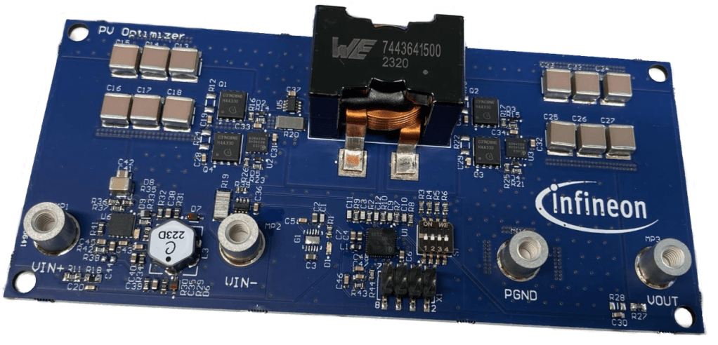
We can use such a Buck-Boost converter now to drive the PV-Solar-Panel at the most lucrative operating point. Figure 4 shows you the Hardware of the Buck-Boost Converter.
MPPT – Algorithm
The next challenge is to design a control algorithm that can track the maximum power point of the solar panel. In classical control applications one has to control a plant at a specific predetermined operation point or trace. However, we do not provide a specific point we would like to be at the maximum, wherever that is.
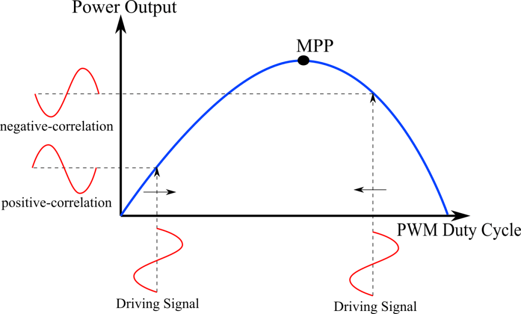
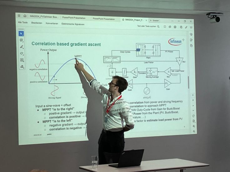
We can find the maximum by estimating the gradient of the current operating point and the walk in the direction of the rising slope. The gradient can be estimated by modulating a small sine wave on top of the control signal.
As seen in Figure 5, if we are left of the MPP the driving-signal (modulated input sine wave) is in phase with the power output and has a positive correlation. However, if we are right of the MPP the power output will yield a 180° phase shifted sine and thus has a negative correlation with the driving-signal. So the correlation can be used to estimate the gradient.
The output signal of the controller is a sine to determine the gradient plus an offset. An Integrator, in Figure 6, provides the offset for the operation point.
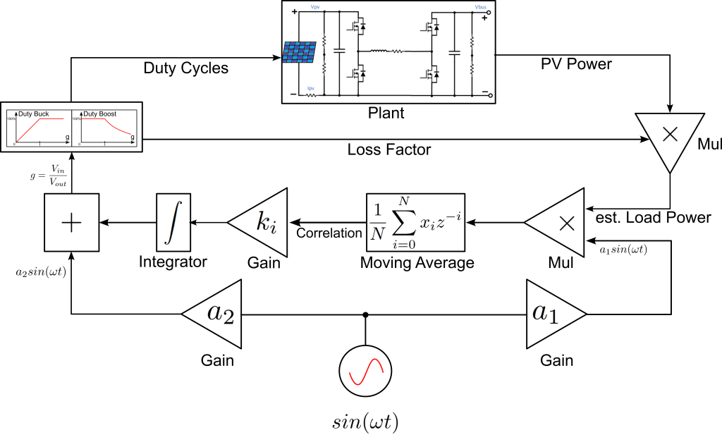
The sine generator is being applied twice, once on the left to be added to the offset of the integrator and once on the right of Figure 6 to be multiplied with the output signal of the plant.
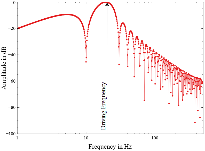
The gradient of the plant is proportional to the correlation of the driving sine with the plant output. The correlation can be done by multiplying the output of the plant with the sine and applying a moving average filter over one period of the driving signal. This correlation approach perfectly filters out the driving frequency (Figure 7) and since it is a summation process it is very resistant to noise.
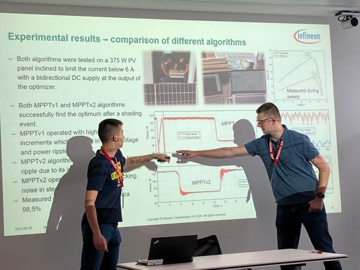
In the following, you can see a simulation of the controller and a plant on the left (Figure 8) compared to the real-world test to the right (Figure 9). Once can see that the controller starts slowly approaching the top and then slows down while approaching the MPP.

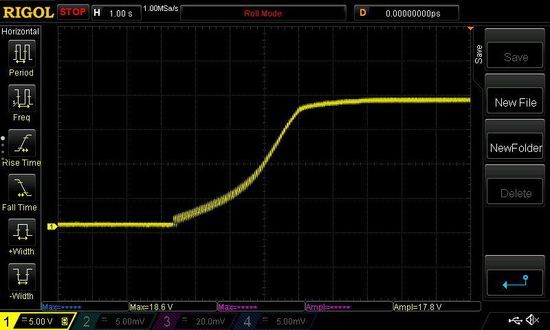
When looking at Figure 5, one can imagine that the slope of the curve not only determines the sign of the correlation but also the amplitude of the output signal. In Figures 8 and 9, one can see that the driving signal starts out quite large, where the plant has a steeper gradient and gets smaller at the MPP where there gradient is zero.
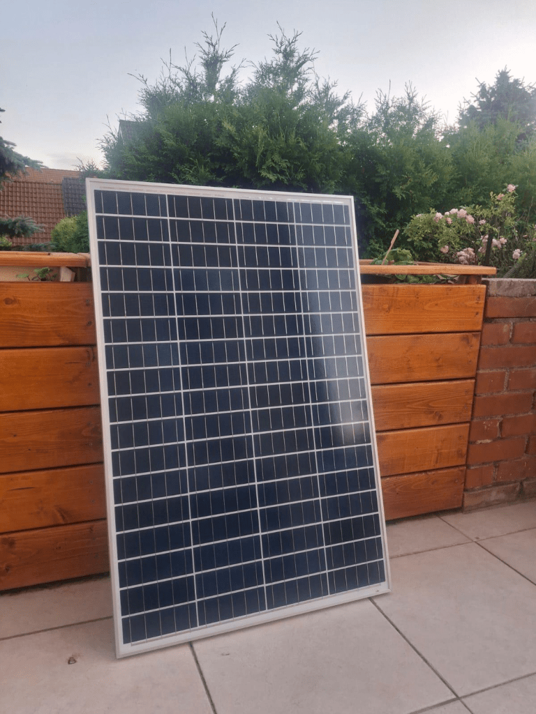
On the left in Figure 10, one can see the solar panel that has been used for testing.
Performance
The performance of that controller is very high since all operations are computationally very inefficient. The integrator is just one addition. The sine generator can be implemented by discretizing the differential wave equation using gausses which results in two multiplications and additions or exact discretisation which is only slightly more expensive and the moving average filter that can be implemented with a complexity of O[1] when accumulation everything that goes in and everything that goes out using a circular buffer. However, the last part only really works for data types with integral precision, otherwise, there might be some numerical errors. For a good fixpoint library supporting C++14, have a look at my GitHub Fixpoint library. It provides a 32 and 64-bit fixpoint with user-definable rational bits. For a math library with a focus on signal and control-system theory have a look at TWMath.
That way, this controller can even be implemented on low power microcontrollers with a low core clock.
Conclusion
This is a relatively neat little controller, that is not too complex has great noise reduction, due to the integrative effects of the correlation, and is very much suited for power electronics where switching noise can be really trouble some. Furthermore, it is computationally inexpensive and can be implemented on low power microcontrollers.
With this approach be also won the Infineon PV-Optimizer Challenge 2024.
Literature
- Stability of extremum seeking feedback for general nonlinear dynamic systems – Miroslav KrsticH, Hsin-Hsiung Wang
- Extremum-seeking control for nonlinear systems with periodic steady-state outputs – Mark Haring, Nathan van de Wouw, Dragan Nešić
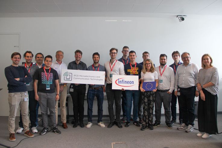
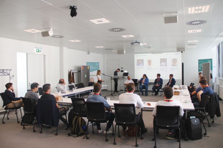
Meeting Infineon
All this was part of a challenge from “Infineon Technologies Austria” in cooperation with “IndustryMeetsMakers” and IPCEI (Important Projects with Common European Interests). As part of this challenge we have had the opportunity to meet, preset our projects and discuss them with experts from Infineon.


Furthermore, Infineon gave us an interresting walk through their different departments and production facilities in Villach. We were shown the process of creating a new chip from the starting idea, the architecture, design requirements, the high-level description and the experts that finally created the chip layout. Especially interesting to see was, that many of the different departments and experts we spoke with were doing processes, exactly like we learned in lectures at my university, TU Wien. Lectures like Analog Integrated Circuits – where we design and calculate analogue transistor circuits and on a high level, Digital Integrated Circuits – where we learned about logical circuits and clocks, Digital Integrated Circuits Laboratory – where we designed our first digital hardware for an FPGA in Verilog, Advanced Course Circuit Design – where we designed our first analog chip in Cadence and HW/SW Codesign – where we designed a CPU with custom hardware acceleration to optimize a specific task (Ray Traceing Rendering).
Then we switched buildings and went to the other side of the street where we had a look into the production facilities of Infineon and could watch first-hand how robots were racing on the ceiling, carrying wafer from one machine to another. Autonomous arms were grabbing wafers and putting them into machines hidden behind walls.
It was fascinating to see so much of what we learned from books or power-point slides coming to life.

Leave a comment