It was always a big dream of mine to not only have a stunning stereo system but to design and build it myself. The speakers are finally finished and in this article, I want to show how I built them and how they work internally. I will go over the whole system explaining everything in detail.
First, when building, a speaker we have to decide how it will look and function in general and then work out the details. I decided on building a tower with three dedicated speakers for low, mid, and high frequencies. Each speaker will be driven actively and has its amplifier. Each amplifier should be adjustable so that we can add more bass, mids, or highs depending on our liking.
I will split this article into the following two parts:
- PART I The Speaker
- PART II The Amplifier
Part I The Speaker
First, we have to think about the frequency range that each of the three speakers is going to play. We, humans, hear roughly from 20Hz to 20kHz, however, we cannot just split this range into three equally long pieces. Since I wanted each one to be adjustable a change in the adjustments should feel natural to our senses. Our senses are not linear, we humans are mostly logarithmical creatures. So we have to split the audible range into pieces with equal logarithmical length. That’s why I chose to use 20 – 200 Hz for the low, 200 to 2k Hz for the mid, and 2k to 20k Hz for the high frequencies, all of those have a distance of one decade. Knowing that we can search for speakers that have a high-frequency response and small changes in Impedance for their selected range.
Speaker Selection
In the following, I will describe the three speakers I have selected:
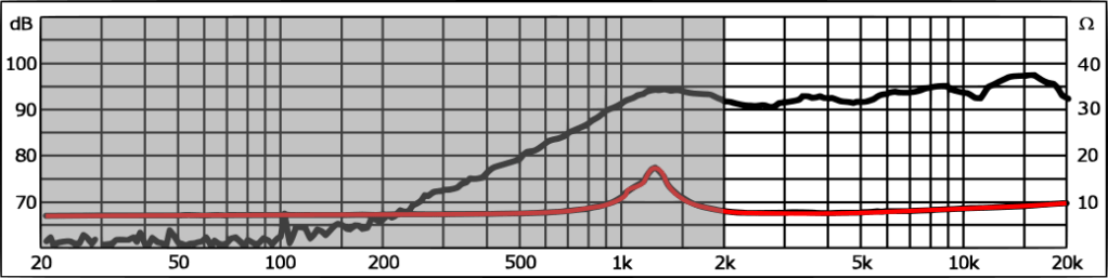
High Tweeter Monacor DTM 104/8
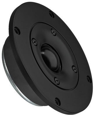
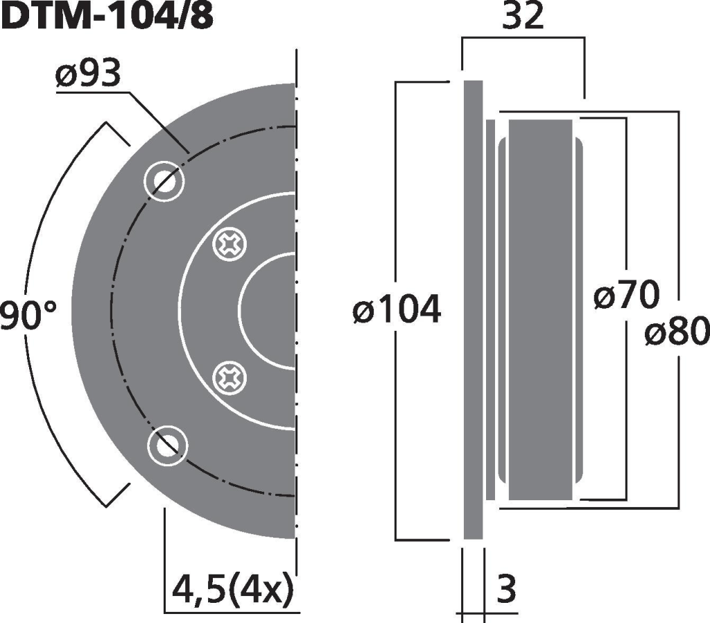
Bildquelle: Monacor
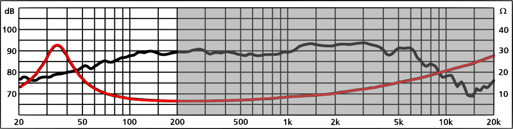
In the black curve, you can see the SPL (Sound Pressure Level). SPL is defined as the pressure ‘p’ measured at a distance of 1m on axis to the speaker expressed in decibel (dB) with a 1W input as can be seen in the following equation.

The reference ‘p0’ hereby is defined as 20µPa. In short, the higher the black curve the louder the speaker is at that frequency.
The red curve describes the magnitude of the input impedance ‘|Z|’ of the speaker. Which is defined as the magnitude of the applied voltage ‘U’ over the current ‘I’. Since the amplifier, that we will discuss in PART II, will output the signal in terms of voltage and not of power we want to replace the current with the power to see the effects.

This means the higher the impedance the less power will be transmitted to the speaker. However, both the impedance and the SPL rise, so the actual overall frequency response of the system will be relatively constant.
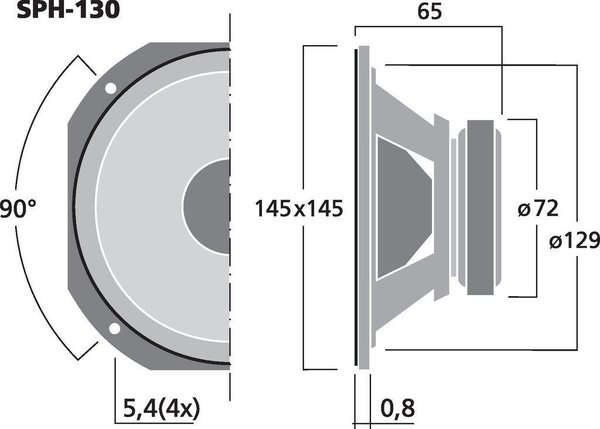
Mid-Range Speaker Monacor SPH130/8
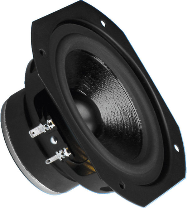
Bildquelle: Monacor
The SPH130 has a very stable SPL in the selected frequency range. However, its impedance is almost twice as high at 2kHz as it is at 200Hz. Higher frequencies will thus be quieter by 3dB. We could boost those frequencies later in the amplifier. However, 3dB over one decade is probably barely noticeable. But we will keep it in mind.
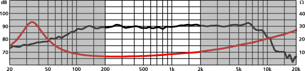
Low-Range Speaker Monacor SPH 175/8
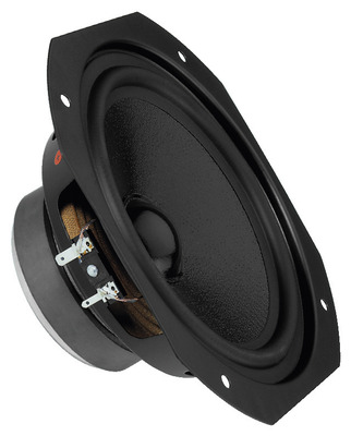
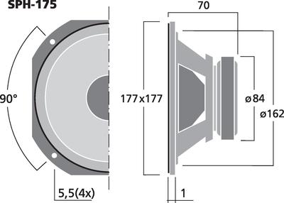
Bildquelle: Monacor
For the low frequencies, I wanted to use a speaker with a wider cone. Because if we want to create high-pressure levels at low frequencies we have to displace a lot of air. If the cone is wider it needs less excursion to create the same air volume displacement.
When looking at the impedance curve you see that it is not very constant and rises significantly around 33Hz. Which is also called the resonance frequency of the speaker. As a result frequencies in between 20 – 60Hz will be played much quieter than frequencies in the range of 100 – 200Hz. The peak of the impedance is about 4 times larger than it is at 200Hz thus resulting in a 6dB drop. Furthermore going lower in frequency the SPL starts to drop rapidly with about 20dB per decade starting at 100Hz. That effect can later be counteracted with an amplifier that will enhance lower frequencies. However, the details may change when the speaker is built into the box.
Speaker Box Design
For my box, I decided to separate all three speakers so each one has its own individual chamber. The low-frequency speaker displaces the largest amount of air and will need the biggest chamber. In addition, a speaker box acts like a high pass filter. That is why we are going to calculate its chamber first and add the other chambers accordingly.
To calculate the speaker box I used the online simulator: Speaker Box Lite.
It is a really powerful tool with a great help wizard that guides you through all necessary steps.
After entering the parameters of the SPH-175/8 the tool recommended that a closed speaker box design will give the best results. So I went for a closed speaker box and designed it for a Qtc of 0.609 – I decided on this value because it is a compromise of a maximally flat amplitude (0.707) and delay (0.57) response and it is bound to go up when I add more support structure later. The Volume of the low-frequency chamber resulted in 18.3L and the internal dimensions are 210mm x 297mm x 293mm. The chamber sizes for the other speakers are not as important and weren’t designed in detail.
What is important, however, is the question if standing waves can propagate in the chambers. Chambers that can contain standing waves will resonate and produce unpleasant sounds. Thus we have to dampen those chambers later. Wool is often used as a dampening material, because it has a lot of friction with itself which will transform the energy of the pressure waves in the chamber into heat. We can calculate the lowest resonance of a room by finding a sinus that when reflected will constructively interfere with itself. The first that will constructively interfere is half of a period long and can be calculated as follows. The largest dimension of all chambers is Lmax = 297mm at an air velocity of vair = 343m/s the first standing half-wave occurs at a frequency of:
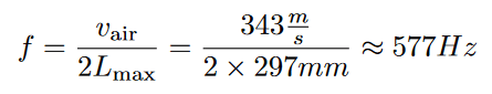
This means that we have to add dampening material to the mid-range speaker (200Hz – 2kHz) that plays this frequency and to the high-range tweeter that plays its harmonics.
Building the Speakers
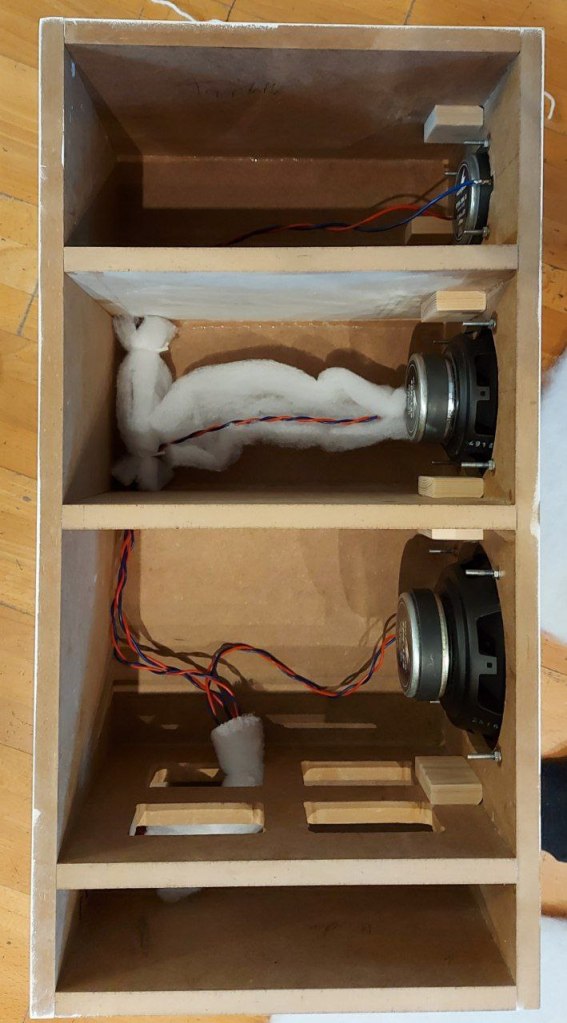
On the left, you can see the inside of the speaker box. Each speaker has its own dedicated chamber. An additional support structure has been added directly underneath the low-frequency speaker to reduce waves through the material. Additionally, you can see in this picture that the wires to each speaker are a twisted pair to reduce electro-magnetic interference and that I am about to cover each wire pair in wool. This is done so that the wires do not produce any noise when hitting the walls of the box or each other.
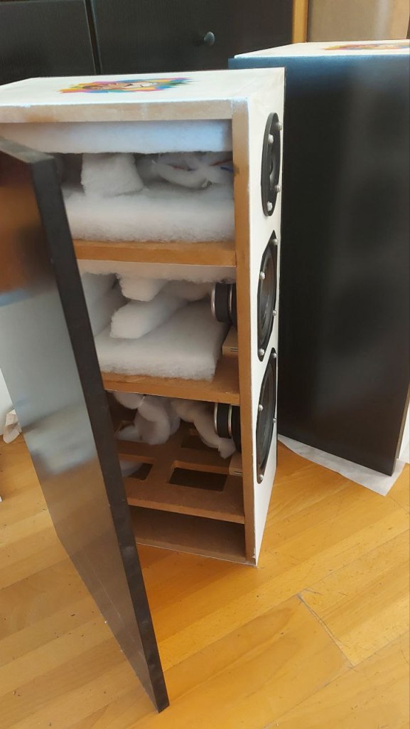
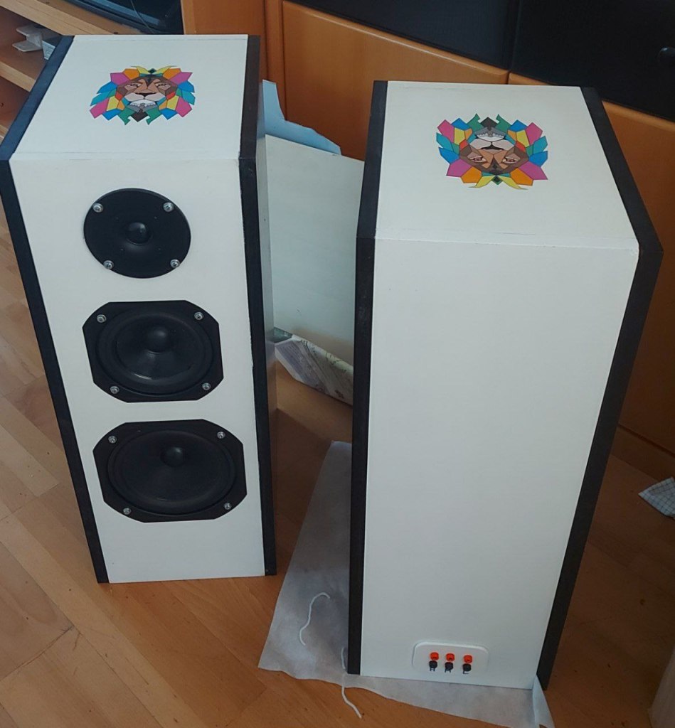
On the right, you can see the inside with the added dampening material. As well as the finished speakers in their black and white design. On the back side, you can see the terminal on the bottom that lets us control each speaker individually. I used MDF wood with a thickness of 16mm.
However, since I think I hear the walls resonating at louder volumes, I would go for a thicker material, at least for the speaker plate, in my next design.
If you are wondering how I applied the colorful lion head on the top: I designed it with the vector graphics tool Inkscape, printed it, put it on a wet layer of transparent gloss paint, and then painted over it again.
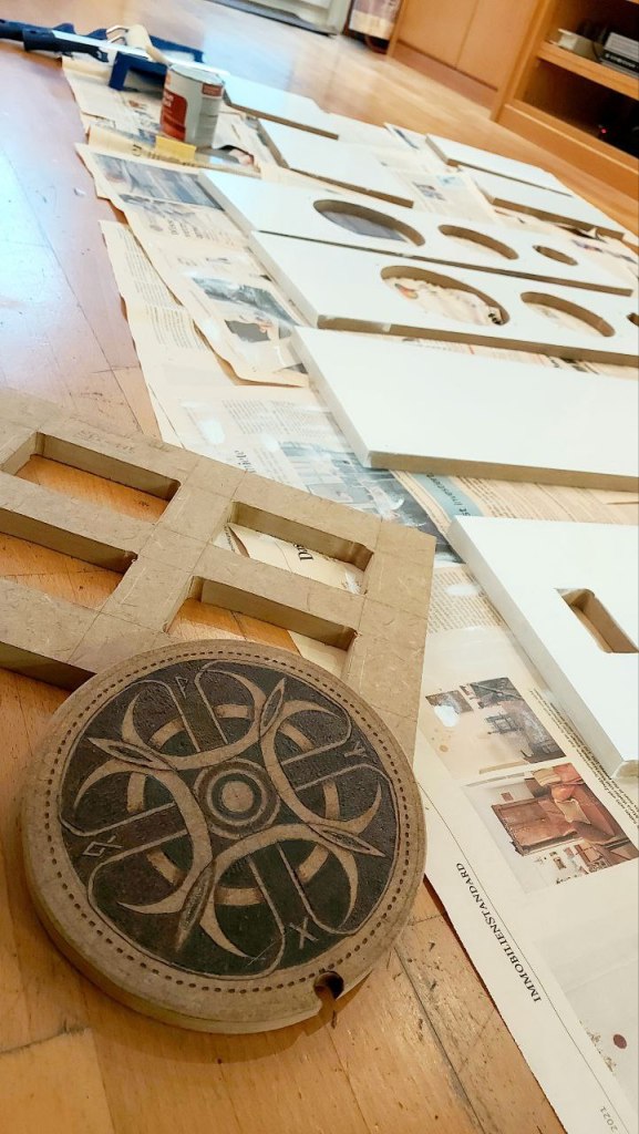
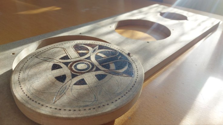
In case you need an idea of what to do with the speaker cutout material – I decided to make a trivet out of them by burning a pattern into them with my soldering iron.